Installation - PROTECTOR 850cz
CONTENTS
Protector Kit contains:
- 1 radar antenna with 3.5 m cable and connector
- 1x GPS antenna with 1.5 m cable and Connector
- 1 Main control unit
- 1 control unit with an embedded GPS SD Card
- 1 x 2 m cable connecting the two controllers
- 1x Power cable with connector
- 1 Multifunction button with 1.5 m cable and Connector
- 1x Speaker with 1.5 m cable and Connector
- 1x Universal mount the radar antenna
- 1 Fasteners for mounting the antenna
- 1x SD card with configuration files, the control program and manuals
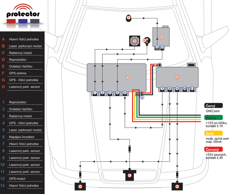
DIAGRAM
Schema connections between system components:
INSTALLATION
-
Protector Installation must be performed only by trained manufacturer's assembly center. For information on available service centers, contact your dealer.
RADAR MODULE ASSEMBLY
-
Radar antenna module is an extremely delicate and sensitive device captures signals that transmits radar and therefore the choice of location for its installation critical to ensure proper function and good sensitivity. The antenna is installed in front of the car, usually a plastic bumper or behind the front grille of the vehicle before the cooler so that the arrow on the antenna facing forward. The ideal is to place the antenna to vent at a height of bumper 30 to 50 cm above the ground and the place where the antenna is not visible from outside the car (the arch under the plastic mlhovkám). If you choose to mount the antenna so that the front bumper cover part of the antenna, make sure the metal is in the bumper reinforcement or other metal (chromium), which would partially or completely antenna highlighted some. Always install the antenna in the vertical position of "standing" when the antenna for use in the CR and SK maximum sensitivity and minimum false alarms.
-
Also need to keep as much distance from the antenna heat sources such as engine cooling and air conditioning, from which the antenna may become warm. Failure to comply with a distance will not be guaranteed due to the correct functionality and increased temperature can cause overheating of the antenna. If you want to avoid these problems, place the antenna away from heat sources or secure access to free flow of air that will cool for driving the antenna. In case of ambiguity in the location of the radar antenna, please contact your dealer.
PICKUP
RADAR ANTENNA
-
Antenna assembly is supplied in original packaging with pre-drilled bracket holes. Due to the stability of the antenna is necessary to use screw clamps on both sides of the antenna! When fitting out of a possible mechanical damage to the antenna, not covered by warranty! The warranty also does not apply to damage caused by improper installation or dismantling equipment Protector (or its components). A manufacturer or seller is not at the same time the additional costs incurred installing or removing equipment.
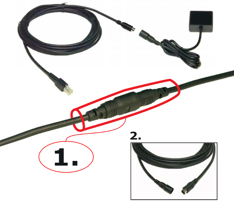
CABLE ANTENNA RADAR
-
Mount antenna with the antenna cable connector connecting the second part. Route the antenna cable to the front bulkhead between the engine compartment and the cab driver. We recommend that you add to your existing wiring and fasten with fastening strips. Cable and connecting the antenna connector is resistant to the environment the engine compartment and allows easy connection and disconnection of the change of mounting an antenna or its replacement. When installing the cable, keep in mind that the cable must not touch the hot parts of the vehicle and must be installed in locations of increased temperature. In particular, it is necessary to avoid any contact with moving parts wiring engine, such as the alternator, propeller or coolers
-
Extension cable to the cab driver to use the original cable gland. If there is not enough space to stretch, it is necessary to drill a hole and needed to stretch the cable end connector. When drilling the hole to keep the utmost care not to damage surrounding cabling, or other part of the vehicle! When stretching be careful also to damage the connector end! After the cable entry hole is necessary to ensure a suitable silicone sealant as necessary to avoid moisture penetration into the vehicle. Also make sure the cable is long enough to reach the desired position. Cable at the sensor and measured 1.7 m cable that connects the sensor to the control unit is 1.8 meters long. A total of 3.5 m cable can be extended by an extension cord (optional) for a further 3 meters.
When connecting cables to use the site to achieve shrink tape. To use the tape shrinkage shrink hot air or lighter.
LASER MODULE ASSEMBLY
- Outdoor sensors - can be installed in the front grille above the bumper of the vehicle or, where appropriate, in the rear of the vehicle. Pay special attention to you during installation damage the cable or connector (cable or damaged connector leads to the removal voids warranty). In order to improve the appearance of the vehicle can be used to cover special sensors plexislo transparent "Perspex". More information is available from your dealer.
The extension cable to the cab driver to use the original cable gland. If there is not enough space to stretch, it is necessary to drill a hole and needed to stretch the cable end connector. When drilling the hole to keep the utmost care not to damage surrounding cabling, or other part of the vehicle! When stretching be careful also to damage the connector end! After the cable entry hole is necessary to ensure a suitable silicone sealant as necessary to avoid moisture penetration into the vehicle. Check that the cord is long enough to reach the desired position. Cable sensor for measuring 1 meter cable that connects the sensor to the control unit is 4 m long. Total 5 meters of cable can be extended by an extension cord (optional) for a further 2.5 meters.
When connecting cables to use the site to achieve shrink tape. To use the tape shrinkage shrink hot air or lighter. Using the supplied double-sided adhesive tape Attach the sensor bracket to the desired position, which offers a clear view forward or backward. If necessary, you can mount additional bend in the desired position. Make sure the sensor is firmly secured to withstand vibration while driving. Also, make sure that the sensor is in a horizontal position (use a spirit level attached) and head directly in front of / behind the vehicle.
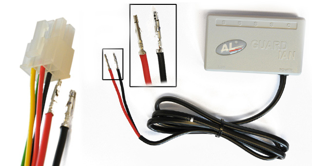
- Controller - is installed in the vehicle interior padding, or under the dashboard of your discretion, but only where it comes into contact with water. Connect the power supply control unit with special pins to the control unit Protector (see Figure HERE ). Note: 1A fuse is located in the control unit. If you require additional insurance can be installed externally on the wiring (not necessary). After the control unit is connected to the unit Protector, connect the sensor to one of the "S" outlets. If you have more than one sensor, connect them all, the order of the sensors is essential. Please also connect the unit's communication cable to the main unit Protector (The Protector marked "laser module", the unit's marked "C".
- Connection with an earlier version of Protector unit's G9 - Protector can also be combined with the unit's older version (version G9). Version attached jammers set PC program on the enclosed SD card in the GPS module.
INSTALLATION
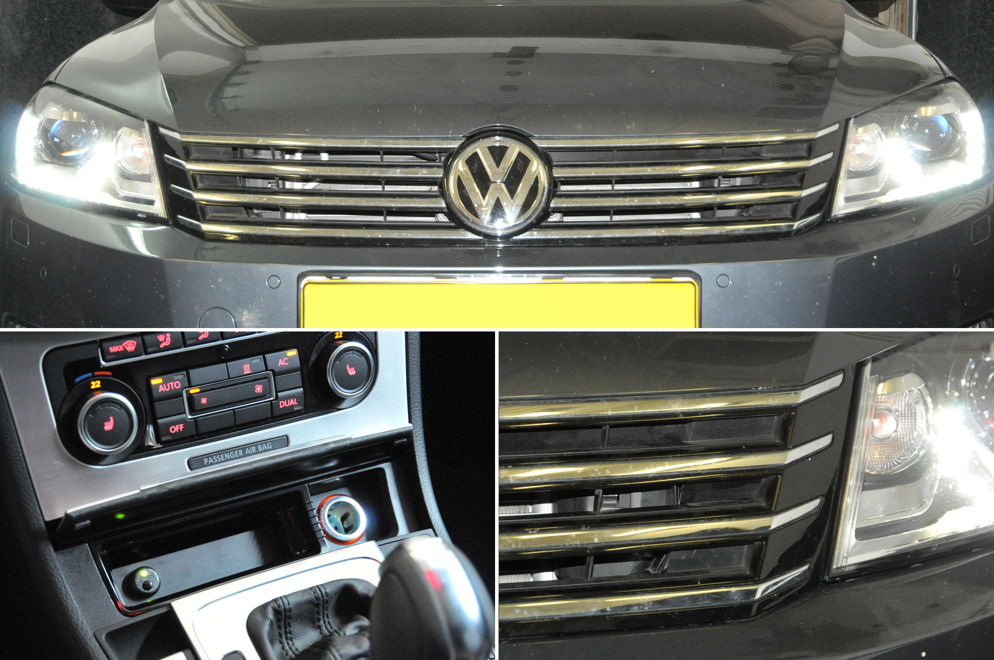
control button
-
Control key position in the location that was visible for the driver and you could comfortably use while driving. For mounting buttons need to drill the installation hole Ř10mm. For installation, we recommend use vacant keys (caps), or other suitable place in view of the driver, possibly in an ashtray or in some of the unused slots in the car.
SPEAKER ASSEMBLY
-
Signaling speaker position on the lower legs of the driver or passenger. The location should be chosen in the context of ensuring the proper volume of the alarm speaker.
GPS ANTENNA INSTALLATION
-
Attach GPS antenna with a suitable adhesive or double-sided adhesive tape so as to ensure the top of the line of sight antennas (labeled Leadtek tear) on the sky. Recommend the best location on the dashboard of the vehicle. If you place the GPS antenna hidden under the dashboard, an antenna must not be overshadowed by metal elements (note the coated and heated windscreens). The function of the GPS antenna can be verified by a blue LED located on top of the GPS antenna and LED on the control unit GPS. If the blue LED on the GPS antenna flashes receives signals from satellites. If the LED is lit, the signal from the satellites is not sufficient. To verify the functionality of the GPS antenna, the vehicle must be outdoors and outdoors, to ensure the GPS reception. The first activation of the antenna is about 1-5 minutes. Indicates the state of the GPS antenna is also possible to monitor the signal LED on the GPS ECU. Description see. on.
INSTALLATION AND CONTROL UNIT CONNECTIION
-
The control unit continuously analyzes the signals from the radar antenna, GPS receiver and control unit evaluates these. The unit is usually placed on the fuse box or the wiring using cable tape or sticking to the free surface using double-sided adhesive tape. Connection of the components is evident, as described on the control unit according to the wiring or connections. Everything is easy to do using sliding connectors.
-
When connecting individual components, set pay great attention to all the connectors are engaged in the appropriate slots
INSTALLATION AND CONNECTION OF GPS CONTROL UNIT
-
This control unit communicates with a GPS antenna and transmits information to the main unit. The GPS unit is inserted SD card, which stores data relating to the setting of the entire device and the GPS database. Place the GPS unit so as to maintain easy access to the flowers inserted SD card. The control unit is also equipped with GPS signal LED. If the LED is green, everything is fine and the unit communicates with the SD card and antenna signal from the GPS satellites. If the LED flashes green, antenna, GPS signal from satellites is not, in this case, verify if the vehicle is not equipped with a heated or plated glass, which blocks out reception from satellites and that the GPS antenna is properly connected / located.
- Warning: GPS unit each time receives and evaluates the signals from the satellites and the time needed for activation is approximately 0-5 minutes from power. So wait this time before you manipulate with an antenna because of expected bad installation.
Other states signaling LED on the GPS unit are:
-
If the LED flashes red, you disconnected or damaged GPS antenna or SD card error occurred (failure data consistency, or not properly inserted into the slot).
-
If for any reason you want with an SD card to handle Always turn off the detector to prevent damage to data stored on the SD card
POWER CONNECTION
-
Protector device is powered via a connector located on the main control unit:
- red wire - +12 V power wire to engage the contact of the vehicle No. 30 (+12 V constant power from car battery)
- black wire - GND-12V (vehicle frame)
- green wire - +12 V power cable to connect the vehicle to contact No.15 (+12 V after ignition key)
- Yellow wire - Alarm output mute switches to GND frame of the vehicle. Connect this wire to the proper input to mute the audio system or car stereo. (Max. output load is 50mA/14, 5v)
Since both the control unit - the main control unit and the GPS unit - they have installed themselves in overcurrent and overvoltage protection, do not be retrofitted to the AC power line current protection devices.
EXAMPLES
wiring
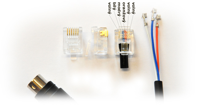
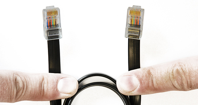
SAMPLE WIRING CONNECTOR MODULE Beltronics
- Connector is used
RJ12W-R (for round wire) - alternatively you can use 4-pin equivalent.
SAMPLE WIRING POWER MODULE unit's
- Cores are used
SAMPLE CONNECTION WIRING MODULE unit's
- Connectors are used
- Cable is used
SPECIFICATIONS
Frequency bands detector
- X-band 10.525 GHz ± 25 MHz
- K-band 24.150 GHz ± 100 MHz
- Ka-band 34.700 GHz ± 1300 MHz
- Ka Narrow 34.0, 34.3, 34.7 and 35.5 GHz ± 80 MHz
Power
- Supply voltage: 11 to 16V DCA) Sleep when taking off button / standby mode / cca.12mA
- Power consumption On mode: approx. 300 mA
- Maximum current consumption in alarm: 450mm / max
- Output mute switches on the floor in alarm max load: 50 mA / 14.5 V
- Disconnect connector radar antenna, GPS antenna and radar antenna itself meet the standard of protection: IP67 (waterproof)
- Operating temperature: -20 to +70 ° C
- Storage temperature: -30 to +80 ° C
Dimensions
- Radar antenna: 95.6 x 79.8 x 93.0mm
- GPS Antenna: 60 x 60 x 90mm
- Control Unit: 21x90 x 65mm
- GPS Controller: 21 x 57 x 73mmf
- User control buttons: o 18 x 6mm
- Speaker: 670 x 740 x 31mm
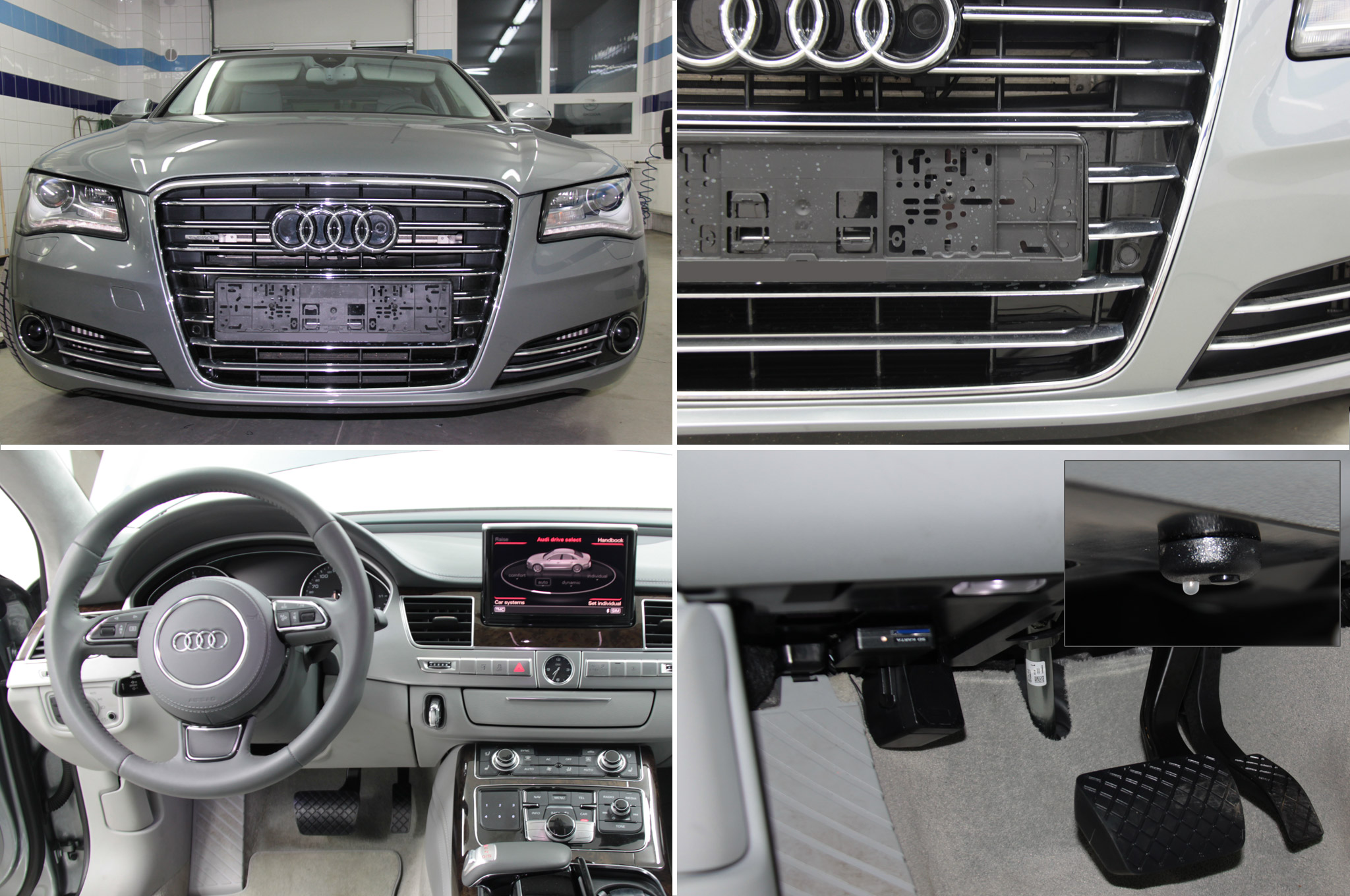
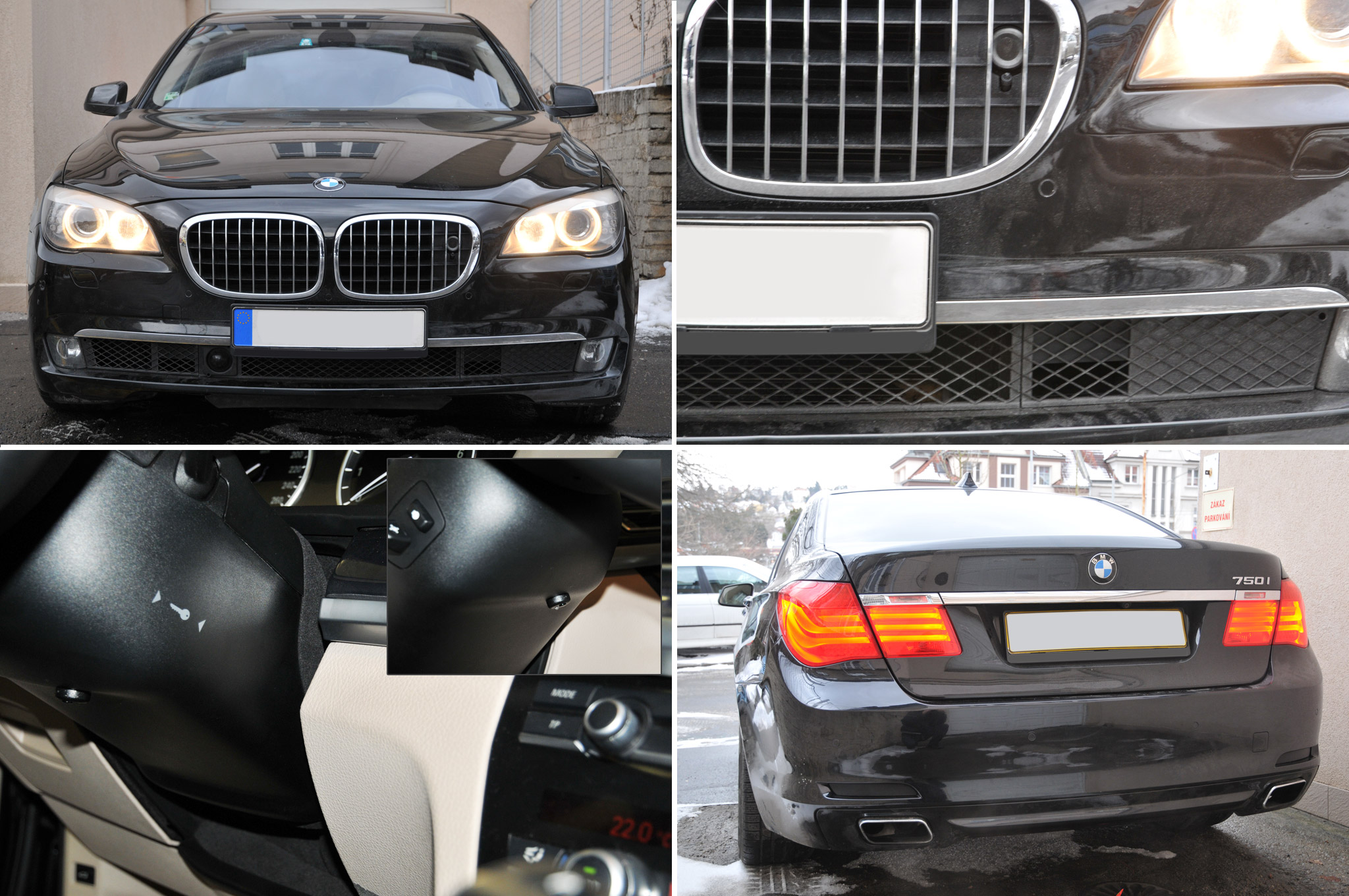
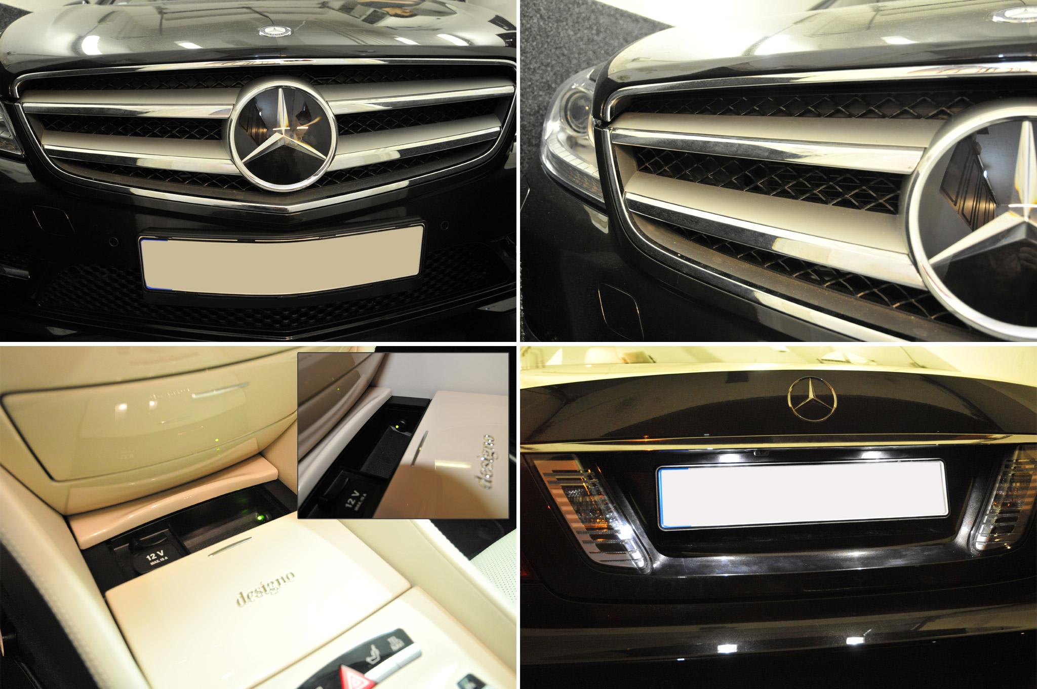
INSTALLATION SAMPLE PHOTOS
AUDI A8
BMW 7
MERCEDES CL
VW PASSAT